1923 Dennis Trailer Pump
![]()

This is a 1923 Dennis trailer pump on solid tyred disk wheels. It is fitted with the Dennis No.2 pump which was only in the second year of use with Dennis. The engine rather than being a White and Poppe unit is a four cylinder Dorman. Rated power output is 20HP. Unfortunately the pump has been partially disassembled for and some parts are missing. The sump has not been in place for many years which has resulted in the crankshaft being rusted into position. The tappet pushers are also siezed solid.
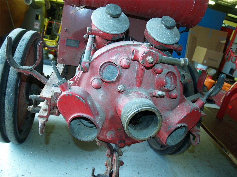
The pump is unusual in that it is fitted with gate valves. These valves are cast into the main turbine cover rather than being separate clack valves cast into the deliveries.
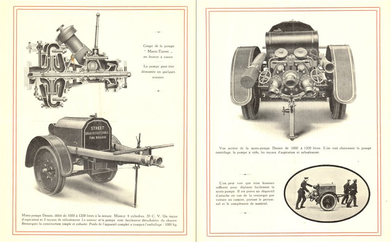
A 1928 advertising brochure shows the this trailer pump in detail. You can see the changed delivery type and also the availability of pneumatic tyres.
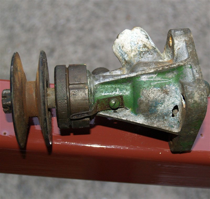
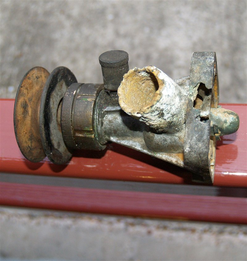
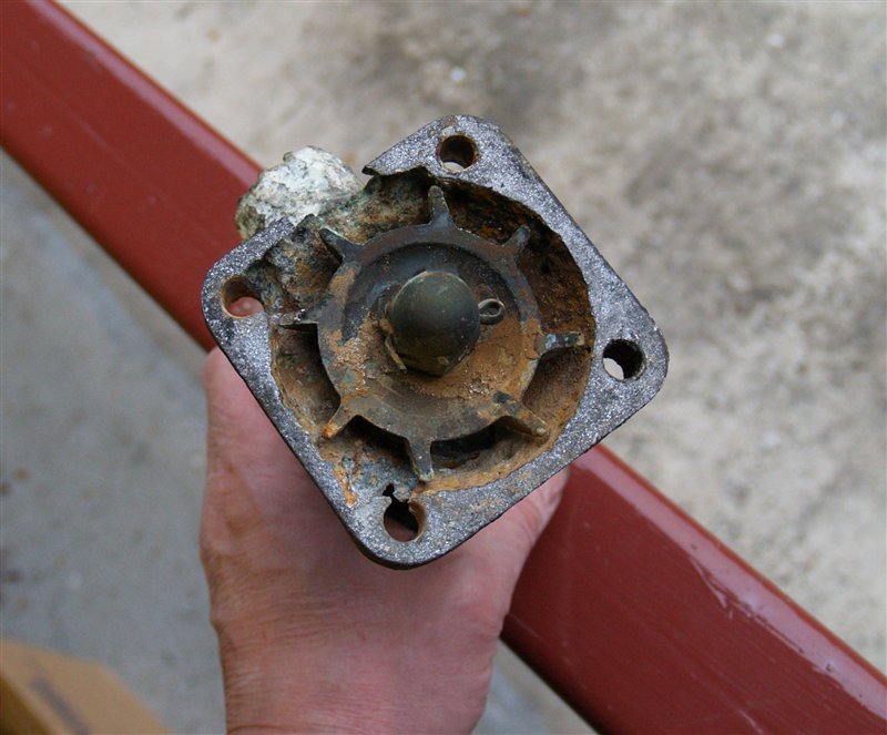
The first desire is to make the engine run and the starting point has been to re-manufacture the engine water pump. As the following photographs show the pump body was badly corroded with holes in several areas.
The traditional route to remake a part like this is to make a wooden pattern and to have the part cast, which repeats the original process of 90 years ago.
It was decided to re-make this part using modern technology. The methods are used are loosely termed 'rapid prototyping' with the emphasis on 'rapid'.The first stage was to draw the original part. Rather than make a 2D drawing the pump housing was drawn as a 3D model using a programme called Solidworks. Dimensions from the original part were transferred to the screen model in under an hour.
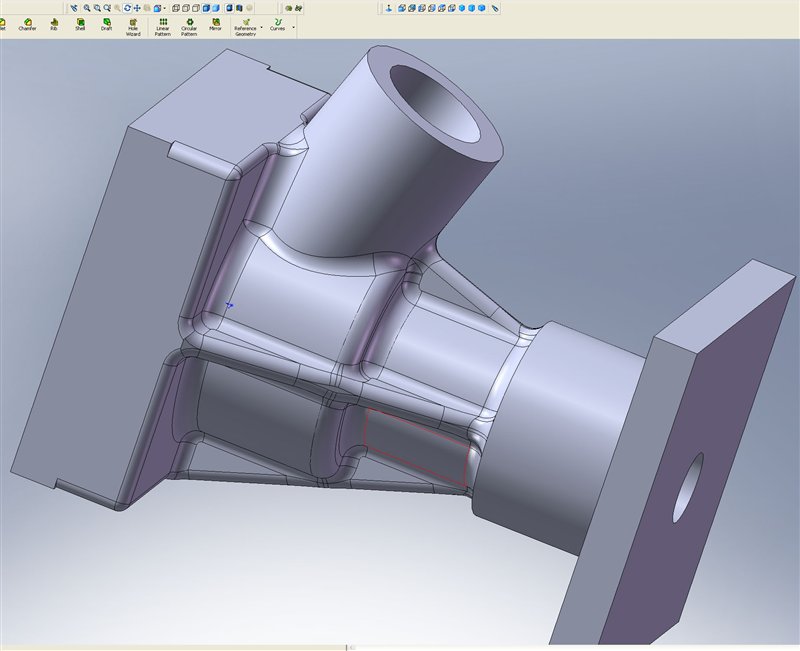
Solidworks is particularly good at 'photo-realistic' output. Below is the water pump model shown with a polished aluminium surface finish.

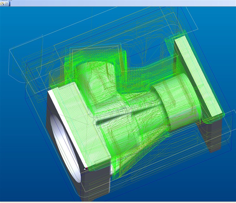
Once the model was complete a programme called 'Edgecam' was used to generate the toolpahs for a CNC milling machine to cut the body of the water pump out from a solid block of aluminium. The curves in the body are achieved by making tiny incremental steps in the z axis. Tool path generation also took one hour.
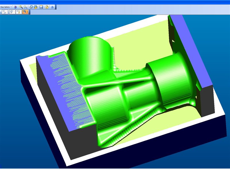
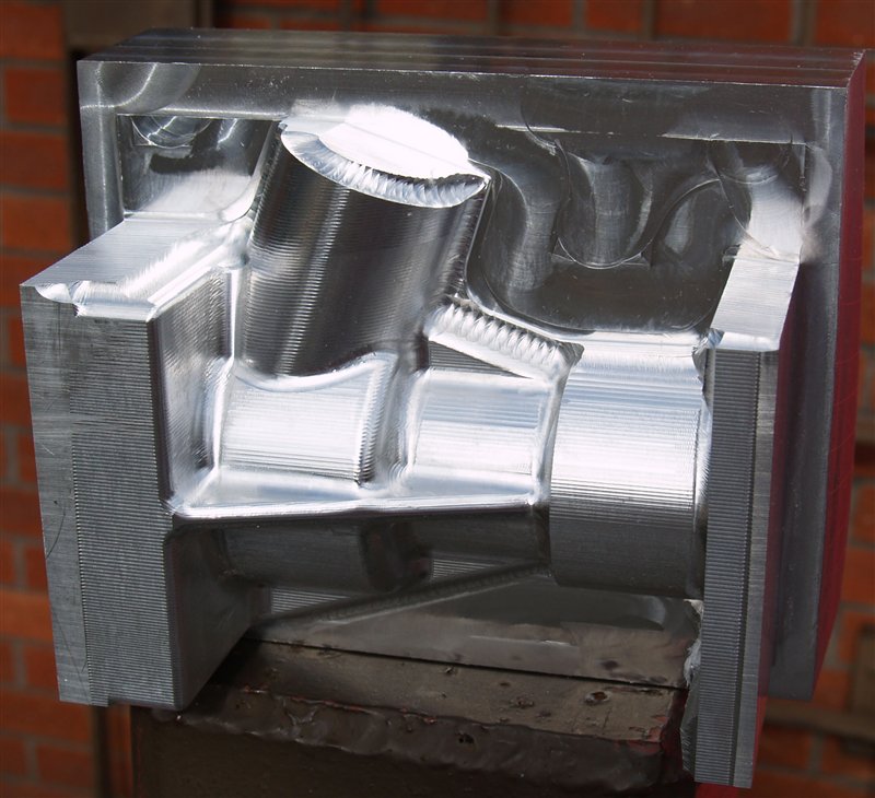
Once the toolpaths are generated the machining sequence can be simulated. The output from the completed simulation is shown below. End cheeks have been placed at either end of the pump to provide surfaces to grip in the machine vice.These are cut off once the machinoing is complete. The steps in the z direction are shown in the simulation. The steps (generating a cusp) were defined so that the cusp height was 0.2mm. Such a size can easily be polished to a smooth finish using 240 grade abrasive paper.
The aluminium block has now been machined on one side. It looks identical to the simulation just as it should!
After the first side was machined the block was turned over and the opposite side was then machined. In this photograph the 'roughing' operation on the second side has just been completed. The finsihing operation is has yet to start. Total machining time was 2 1/2 hours per side.

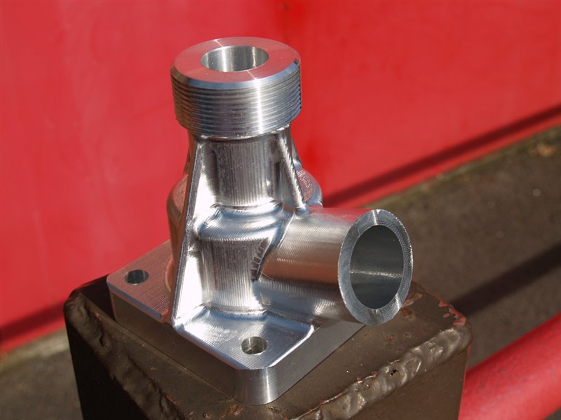
This is the completed part. Additional operations bored the body for the pump shaft and added the thread which takes the gland nut.
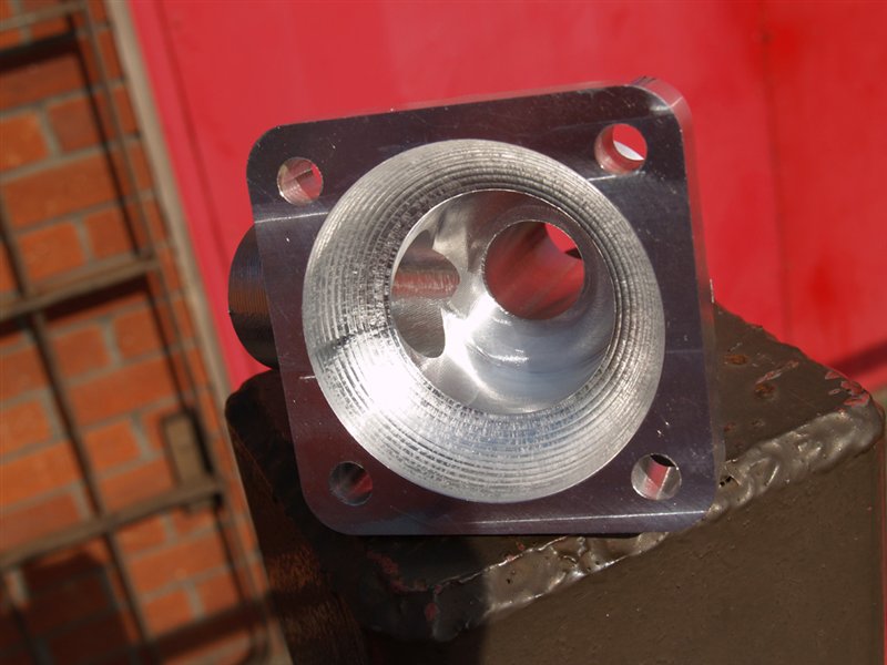
The internal impeller cavity had to be convex. Although this could have been produced on a lathe the CNC milling machine was used yet again.
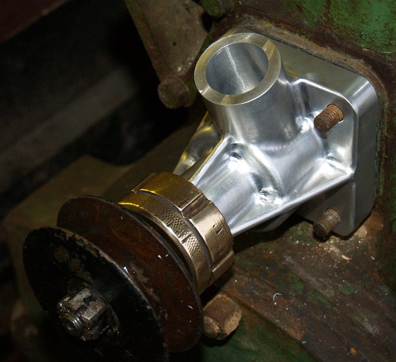
Finally the surface of the body of the pump was polished with abrasive paper to remove the marks left by the milling cutter. The body was re-assembled with a new phosphor bronze bush and should now hopefully last for another 100 years.
For the next stage of the restoration CLICK HERE
![]()